DEFINITION
A free load differs from a ‘regular load’ by the fact that it is NOT attributed as an additional data to a specific 2D member. A free load can be created at an arbitrary position in space, and afterwards the user can specify to which element(s) the projection of this load is attributed to.
Attention: The geometry of a free load is always inputted in the active working plane (XY, XZ or YZ) of the current UCS. It is thus necessary to adapt the UCS in advance and set up the active working plane.
Tools > UCS
A free load can load all elements which are cut by the projection of the free load. Which elements will be actually loaded by the free load, depends on the parameters Select and Validity.
Select
- Auto
All the elements, which correspondence with the validity, will be loaded.
- Select
User choose the elements, which will be loaded, via an action button (chosen elements must be in the scope of the validity).

Figure 1: Update 2D members selection.
Validity
- All
All the elements, which are cut by the projection of the free load, can be loaded.
- -Z
Only the elements situated under the free load (situated in the half-space defined by the negative Z direction of the UCS at input) can be loaded.
- -Z (incl. 0)
Only the elements situated under or in the plane of the free load can be loaded.
- Z = 0
Only the elements situated in the plane of the free load can be loaded.
- +Z (incl. 0)
Only the elements situated above or in the plane of the free load can be loaded.
- +Z
Only the elements situated above the free load (situated in the half-space defined by the positive Z direction of the UCS at input) can be loaded.
- From – to.
Loaded elements are defined by spectrum of Z direction of the UCS at input.
EXAMPLE
An apartment building, where it is likely that the same load configuration acts on more than one storey floor.
Let’s suppose: Four plates situated right above each other, and a free surface load inputted exactly IN the plane of the 3rd plate.
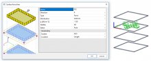
Figure 2: Surface force free.
1) Select = Auto, Validity = All / Z = 0


Figure 3: Validity All and Z = 0.
2) Select = Auto, Validity = +Z / -Z


Figure 4: Validity +Z and -Z.
3) Select = Auto, Validity = +Z (incl. 0) / -Z (incl. 0)

Figure 5: Validity +Z (incl. 0) and -Z (incl. 0)
4) Select = Select (2nd and 4th slab is selected), Validity = All


Figure 6: User selection.
For load generation use action button Generate loads (free load must be selected).
![]()
Figure 7: Generate loads.
Original load can be displayed via action button Display original load.
Tip: User can display generated, original or generated + original load via: Set view parameters for all > Load / masses > Display loads > Generators
Main menu > Calculation, Mesh > Calculation > Test of input data
Main menu > Calculation, Mesh > Calculation > Linear analysis
Main menu > Calculation, Mesh > 2D data viewer > Surface loads

Figure 8: 2D data viewer.
