With the module esa.07 General Cross-section (old protection) or sen.05 General cross-section editor (cloud protection) is possible to import a cross-section from a *.dwg or *.dxf file into SCIA Engineer.
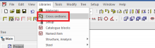
Starting from the menu ‘Libraries’ > ‘Cross-sections’ you can add to your project a new cross-section, type ‘General’:
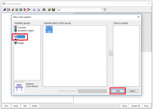
After clicking on [Add] the window ‘Cross-section editor’ opens.
You will notice the different options right away: in addition to the import of a dxf/dwg file, it is also possible to enter the desired geometry yourself based on polygons or an existing section from the library. Futhermore the dimensions can even be parameterized.
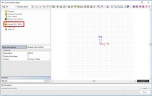
Choose now for the option ‘Import dxf/dwg’ and open the concerned file. The import of a cross-section requires the following steps.
- It is necessary to create a polygon from the loaded cross-sectional drawing because cross-section breaks into curves. Using the function „Connest single curves to closed polygons” and the „Select curves” button, use the left button mouse to select all curves from which to create polygons.
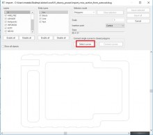
- After selecting the curves, use the „Connect curves” command

- The program will display a report about the created polygons and any errors. You must correct the errors in the original drawing. Close conneting curves via button „End„.

- Select mode: Polygons
Left-click button of mouses to mark the outer polygon:

- Select mode: Polygonal openings
Left-click button of mouses to mark the polgonal openings:

- Import the selected cross-section via the „Imported selected” button:

- Select cross-section material:

- Select the phase at which the hole is formed.

- Select the insertion point in the Cross-section editor dialog

TIP: Take care to define in the source file all of the outlines as polylines, and to define each circle segment as an arc through 3 points (not approximated by lots of straight lines).
TIP You can insert thin-walled cross-sections in the same way.

- After clicking on [Close], the following result is obtained:

Click in this window on [Update] to show the properties of the cross-section, calculated by SCIA Engineer based on standard formulas known from basic mechanics.
To retrieve more correct results for the shear and torsion properties, it’s recommended to select the option ‘FEM analysis’. In that case some calculations are done based respectively on the theories of Grasshof-Zuravski and Prandtl.

TIP: This new cross-section – possibly together with a whole set of cross-sections – can also be saved to a database file (*.db4) via the ‘Save to file’ icon. Afterwards it can be loaded to any SCIA Engineer project, by means of the ‘Read from file’ icon.

