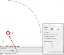
The Rotate icon is situated on the Geometry manipulations toolbar:
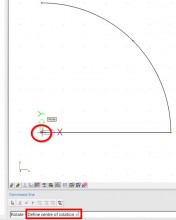
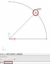
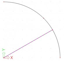
The rotation of the member can be done by vectors. The user needs to determine 3 points.
1st point is the center of rotation (common point for both vectors).
2nd point is the start point (this point determines the first vector).
3rd point is the end point (this point determined the second vector).
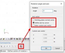
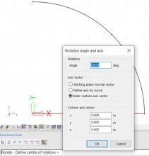
However, in a 3D environment, there’s a choice between three more options how to rotate a member:
1) WORKING PLANE NORMAL VECTOR
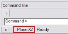
This means that the rotation axis (= a direction vector) is defined perpendicular to the active working plane. The active working plane can be chosen at the bottom of the Command line:
If for instance the active working plane = Plane XY, the rotation will be done around the Z axis of the GCS (or active UCS). Furthermore, only the center of rotation has to be defined.
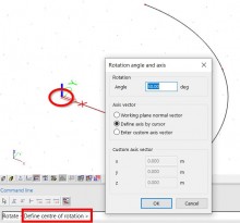
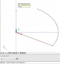
2) DEFINE AXIS BY CURSOR
In this case 2 points on the rotation axis have to be selected, or their co-ordinates have to be entered on the Command line.
It might be convenient to select the first point with the cursor, and to use subsequently relative co-ordinates. E.g. “@0 1 0“: the ‘at’-sign indicates that the co-ordinates (0 1 0) have to be taken relatively with regard to the first point.
3) ENTER CUSTOM AXIS VECTOR
In this case the rotation axis is defined as a direction vector with regard to the origin (0 0 0). If for instance 0 / 0 / 1 is filled in, it means that the Z axis of the GCS (or active UCS) has been chosen as rotation axis.
