A node is the simplest entity applied in SCIA Engineer. A node is the basic element and defines other entity types. For example, a 1D member is defined primarily by its two end-points that are nothing else but two nodes.
Each node has got some properties including:
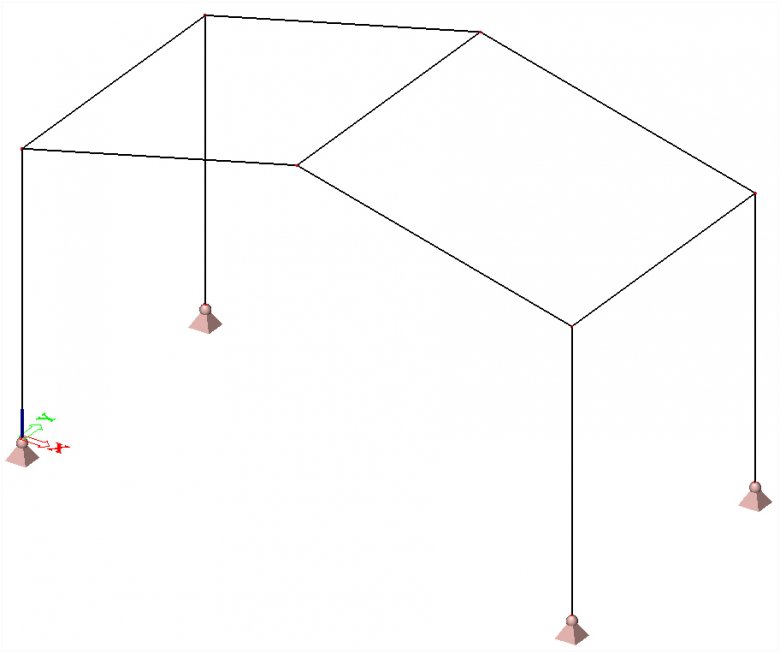
- its position in the modelling space (i.e. coordinates)
- the nodal coordinate system (used to define the direction of direction-related properties such as degrees of freedom)
By default, the local coordinate system (LCS) of a node follows the global coordinate system (GCS).
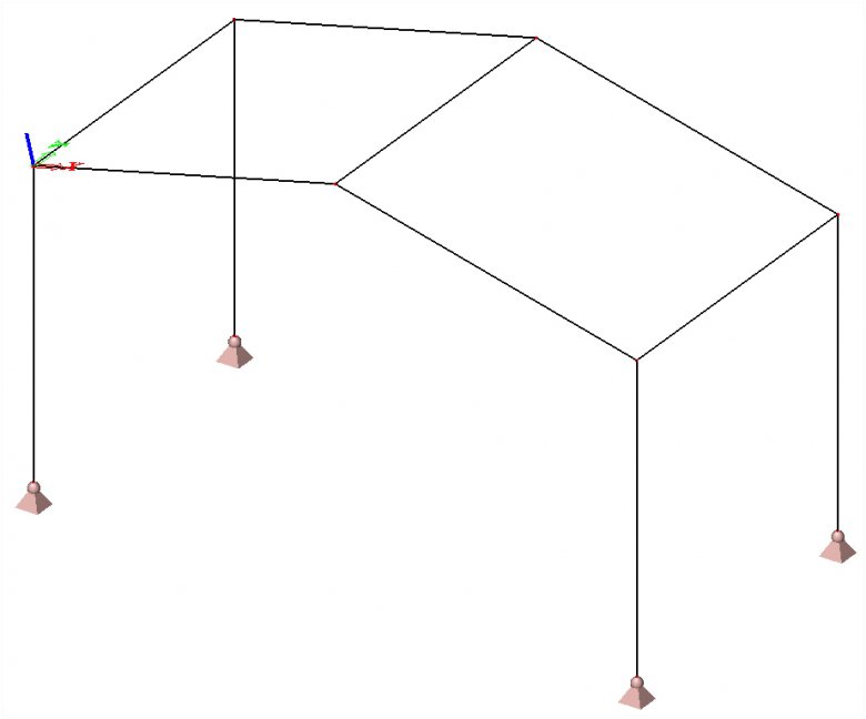
It is possible to define another orientation of the LCS of a node and specify that additional entities follow this coordinate system specified by the user.
DEFINING THE LCS OF A NODE
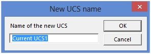
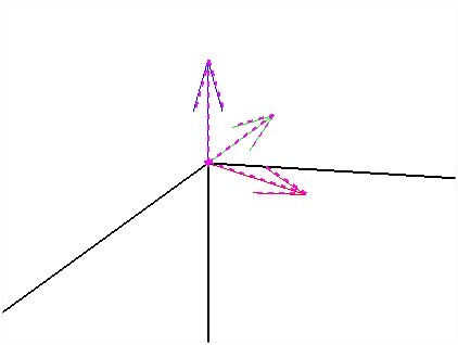
- Use the UCS Manager to create a new user coordinate system. Define the coordinate system in such a way so that its axes are oriented in the direction required for the orientation of the LCS of the nodes.

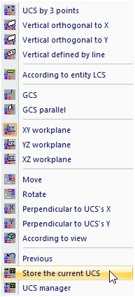
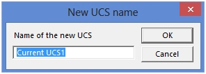
- Save the current UCS via Tools > UCS > Store the current UCS.

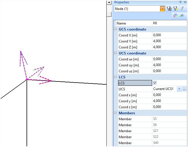
- Select the node (or nodes) where the local coordinate system should be applied (the local axes of a node can be made visible through View Parameters).
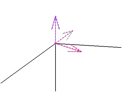
- In the property window you can tick the option LCS. The dialogue then offers a list of defined user coordinate systems. Select the UCS that is adequate for the selected nodes. That means the UCS whose axes are oriented in the direction of the intended local coordinate system of the node or nodes.

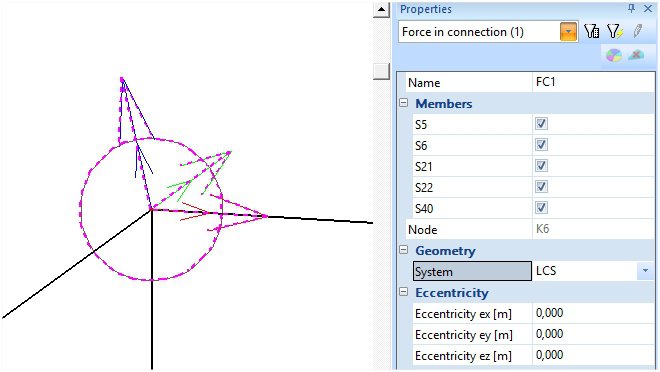
EXAMPLE: DISPLAYING THE CONNECTION FORCES FOR THE LCS OF A NODE
Generally, the user will apply the Connections module for the design and checking of connections in the structure. However, it may sometimes be useful to perform a separate design and fast checking of an individual joint manually. SCIA Engineer provides a simple and fast determination of internal forces acting in selected nodes.
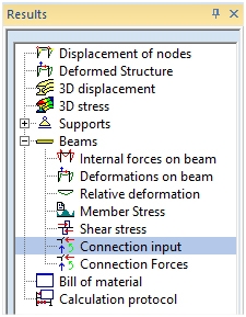
When inserting the Connection input, it is necessary to choose the LCS in the properties.
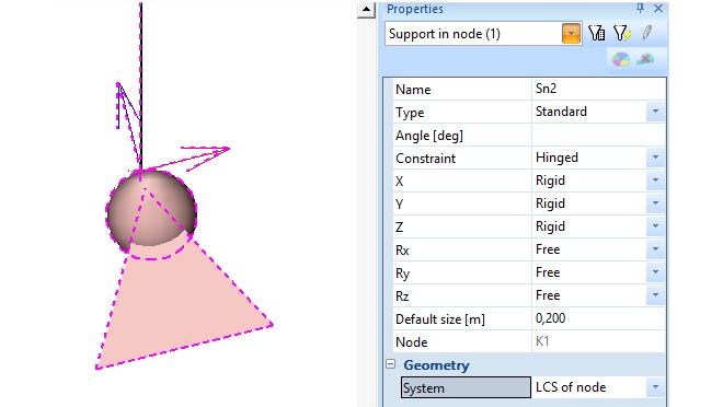
EXAMPLE: DEFINING A SUPPORT FOR THE LCS OF A NODE
A nodal support as well as a point support on a 1D member may be oriented in the global coordinate system or the local coordinate system of the node. It can be chosen in the properties of the support.