Different types of co-ordinate systems are used in SCIA Engineer.
These are important for the modeling of the structure and the definition of loads and supports, and of course also for the interpretation of the results.
Remark: The axes have fixed colors, namely X axis = red, Y axis = green, Z axis = blue.
1) GCS (= GLOBAL CO-ORDINATE SYSTEM)
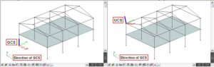
The GCS is the co-ordinate system which is visible and activated when creating a new project. The GCS origin and the directions of its axes are fixed and cannot be modified.
The directions of these axes are shown at any time at the bottom left corner of the model space.
2) UCS (= USER CO-ORDINATE SYSTEM)
The UCS is a co-ordinate system defined by the user, and overwrites the GCS. (The GCS can in fact be seen as a special case of the UCS.)
A UCS can be created and adapted via the ‘UCS’ icon in the ‘Tools’ toolbar:
![]()
At any moment it’s possible to re-activate the GCS, also via this icon.
All co-ordinates entered via the Command line, relate to the UCS activated at that moment.
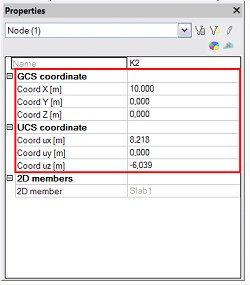
The properties menu of a node always shows its co-ordinates with regard to the GCS and with regard to the active UCS:
3) LCS (= LOCAL CO-ORDINATE SYSTEM)
Each structural entity (e.g. 1D member, 2D member, node) in SCIA Engineer has its own local co-ordinate system.
For 1D members the x axis of the LCS always coincides with the length axis of the beam, and is positive in the direction from beginning to end node.
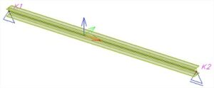
The orientation of the x axis can be reversed by swapping beginning and end node, e.g. via the ‘Reverse orientation’ icon in the ‘Geometry manipulations’ toolbar:
![]()
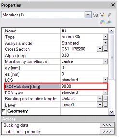
The local y and z directions can be adapted if desired, by means of a ‘LCS rotation’ via the Properties menu of the 1D member:
For 2D members the z axis of the LCS is always perpendicular to the element plane.
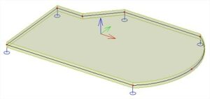
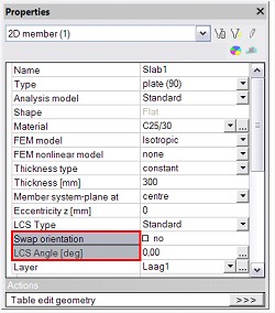
The sense of the z axis can be inverted by selecting the option ‘Swap orientation’ in the Properties menu of the 2D member. Also an ‘LCS angle’ can be entered to define a rotation of the local x and y axes around the local z axis:
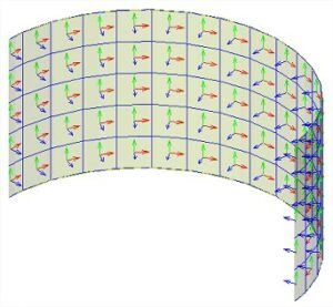
Furthermore a distinction has to be made between the LCS of a 2D member, and the LCS of an element of the finite element mesh.
Each mesh element also has its own local co-ordinate system. Also here the z axis is always perpendicular to the element plane. For the mesh elements of a curved 2D member, we can find for instance the following result: