DEFINITION
Both ‘Alpha’ and ‘LCS Rotation’ are properties of a 1D member, which allow to input an angle in [deg] to define a rotation of the 1D member’s cross-section around itself (around its local x axis).
- ‘Alfa [deg]’ is available as well in a 2D as a 3D environment.
Entering a value here has the following result:
The cross-section is rotated around the local x axis of the 1D member, but the LCS isn’t. So the direction of the local y an z axes doesn’t change.
- ‘LCS-rotatie [deg]’ is only available in a 3D environment (Frame XYZ or General XYZ).
Entering a value here has the following result:
The cross-section as well as the LCS is rotated around the local x axis of the 1D member.
Remark: LCS stands for Local Co-ordinate System.
EXAMPLE
The example consists of 3 beams with the same cross-section. Their LCS is shown by activating the View Parameters.
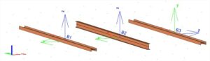
Figure 1: LCS of 1D member
- Beam B2 (in the middle) is the original one, with Alpha and LCS Rotation both = 0 deg.
- For Beam B1 (at the left) Alpha = 90 deg, while for Beam B3 (at the right) LCS Rotation = 90 deg.
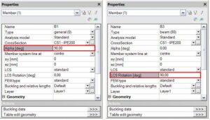
Figure 2: Alpha and LCS rotation of 1D member
Remark: for structure types with limitations (Wall XY, …) the possibilities for alpha and/or LCS-rotation are limited or the parameter(s) are not available.
