Load types available in a particular project may depend on the type of project (2D, 3D, etc.) and on the functionality adjusted for the project. The number of available load types is really large. In this article, we introduce the effect of prescribed displacements for specific points in the structure.
TRANSLATION OF SUPPORT
A node of the structure may be subjected to a prescribed displacement. In such a case, the user defines the direction and magnitude of the known displacement.
Parameters have the following meaning:
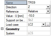
- Name
The name is used for the identification of the entity. - Direction
The direction specifies the direction in which the support „settles”. - Reference
Absolute: The value (below) is input in absolute value related to the origin of the global coordinate system.
Relative: The value (below) is input in relative value related to the position of the support. - Value – U
Specifies the value by which the support is translated. - System
The direction is always defined in the local coordinate system of the support (informative).
The translation of support can be defined ONLY in fixed supports; it cannot be defined in flexible and non-linear supports.
EXAMPLE
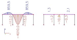
This example demonstrates the difference between absolute and relative reference.
Let us assume a simple three-span frame with supports as shown in the picture.
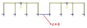
We have two identical frames: the left one for the absolute translation of the support, the right one for the relative translation. The global Z-coordinate of the lower supports is equal to zero, i.e. the supports are located in the global XY-plane.
The translation of a support is assigned to the support located in the middle of the middle-span beam.
The translation in the left frame is input with the following values:

The right variant with the following parameters:
The difference between the absolute and relative reference can be clearly seen in the last picture (the height of the frame is 4 meters).
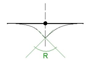
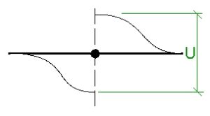
TRANSLATION OF A POINT ON BEAM
A point of the structure may be subjected to a prescribed displacement. The displacement means that the 1D member is „torn apart” and one part of the 1D member is lifted up while the other part is pushed down. The imposed load is clear from the picture below. The defined magnitude is equal to the distance of „torn-end-points” of the 1D member.
ROTATION OF SUPPORT
A node of the structure may be subjected to a prescribed rotation. In such a case, the user defines the direction and magnitude of the known rotation.
The rotation of support cannot be defined in flexible and non-linear supports.
ROTATION OF A POINT ON BEAM
A point of the structure may be subjected to a prescribed rotation. The rotation means that the 1D member is „cracked” and both parts are bent. The imposed load is clear from the picture below. The defined magnitude is equal to the angle between the tangents to the two parts of the 1D member.